Power Factor Calculator
Power Factor: -
Status: -
Reactive Power (kVAR): -
Required Capacitor (kVAR): -
Power factor plays a crucial role in electrical system efficiency, yet many facilities operate with poor power factor conditions that drive up energy costs and reduce equipment lifespan. Whether you’re an electrical engineer designing a new system or a facility manager looking to reduce electricity bills, understanding and calculating power factor is essential for optimal energy management.
Our comprehensive Free Power Factor Calculator 2025 simplifies complex electrical calculations while providing the detailed analysis needed for effective power factor correction. This advanced tool goes beyond basic calculations to deliver actionable insights that can significantly impact your facility’s energy efficiency and operating costs.
Understanding Real, Reactive, and Apparent Power
Before diving into power factor calculations, it’s essential to understand the three fundamental types of power in AC electrical systems.
Real Power (kW) represents the actual power consumed by electrical equipment to perform useful work. This is the power that lights your facility, runs your motors, and operates your equipment. Real power is measured in kilowatts (kW) and directly correlates to your energy consumption costs.
Reactive Power (kVAR) is the power that flows back and forth between the source and reactive components like inductors and capacitors. While reactive power doesn’t perform useful work, it’s necessary for creating magnetic fields in motors and transformers. Reactive power is measured in kilovolt-amperes reactive (kVAR).
Apparent Power (kVA) combines both real and reactive power and represents the total power supplied by the electrical source. Apparent power is calculated using the formula: S = √(P² + Q²), where S is apparent power, P is real power, and Q is reactive power.
The relationship between these three power types forms the foundation for power factor calculations and directly impacts your electrical system’s efficiency.
The Importance of Power Factor
Power factor significantly affects both operational costs and system performance. A poor power factor means your electrical system draws more current than necessary to deliver the required real power, leading to several costly consequences.
Utilities often impose power factor penalties when facilities operate below acceptable thresholds, typically 0.90 or 0.95. These penalties can add 10-25% to your monthly electricity bill. Additionally, poor power factor increases current flow through your electrical distribution system, causing higher losses in cables and transformers, increased voltage drop, and premature equipment failure.
From an environmental perspective, improving power factor reduces the total current demand on the electrical grid, contributing to more efficient energy distribution and reduced carbon footprint.
Common Causes of Low Power Factor
Several factors contribute to poor power factor in electrical systems. Inductive loads are the primary culprit, with electric motors being the most common example. Motors typically operate at:
- Full load: 0.8-0.9 power factor
- Partial load: 0.2-0.3 power factor
- No load: Near zero power factor
Other common causes include transformers operating under light load conditions, fluorescent and HID lighting systems, welding equipment, and variable frequency drives (VFDs). Harmonics introduced by non-linear loads can also distort the current waveform, effectively reducing power factor.
Introducing Our Free Power Factor Calculator 2025
Our Free Power Factor Calculator 2025 stands out from competitors by offering comprehensive analysis with user-friendly operation. Unlike basic calculators that only provide simple power factor values, our tool delivers detailed insights with downloadable reports for thorough analysis.
Key features that set our calculator apart include:
Advanced Calculation Capabilities: Supports both single-phase and three-phase systems with precise calculations for real power, apparent power, reactive power, and capacitance requirements for power factor correction.
User-Friendly Interface: Designed for professionals at all experience levels, from seasoned electrical engineers to facility managers just beginning to understand power factor concepts.
Comprehensive Reporting: Generate detailed reports with step-by-step calculations, formulas used, and recommendations for improvement that you can download and share with team members or contractors.
Accurate Correction Estimates: Provides precise capacitance calculations for effective power factor correction, helping you select the right equipment for your specific application.
How to Use Our Power Factor Calculator
Using our calculator is straightforward, but understanding the inputs ensures accurate results. Here’s a step-by-step guide:
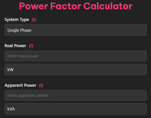
Step 1: Select System Type
Choose between single-phase and three-phase calculations based on your electrical system configuration.
Step 2: Enter Electrical Parameters
Input voltage (V), current (A), and real power (kW) measurements. For three-phase systems, specify whether you’re using line-to-line or line-to-neutral voltage values.
Step 3: Specify Target Power Factor
Enter your desired power factor, typically 0.95 for most commercial and industrial applications.
Step 4: Review Results
The calculator provides immediate results including current power factor, apparent power, reactive power, and required capacitance for correction.
Step 5: Download Report
Generate a comprehensive report with all calculations, formulas, and recommendations for future reference.
Practical Examples and Real-World Applications
Example 1: Single-Phase Motor Analysis
Consider a single-phase motor operating at 240V, drawing 10A with a real power consumption of 1.8 kW.
Step 1: Calculate apparent power
S = V × I = 240V × 10A = 2.4 kVA
Step 2: Calculate power factor
PF = P/S = 1.8 kW / 2.4 kVA = 0.75
Step 3: Calculate reactive power
Q = √(S² – P²) = √(2.4² – 1.8²) = 1.56 kVAR
This motor operates at a 0.75 power factor, indicating significant reactive power consumption that could benefit from correction.
Example 2: Three-Phase Industrial Load
A three-phase industrial load operates at 480V line-to-line voltage with a line current of 20A and real power consumption of 15 kW.
Step 1: Calculate apparent power (three-phase)
S = √3 × V × I = 1.732 × 480V × 20A = 16.63 kVA
Step 2: Calculate power factor
PF = P/S = 15 kW / 16.63 kVA = 0.90
Step 3: Calculate reactive power
Q = √(S² – P²) = √(16.63² – 15²) = 7.24 kVAR
This system operates at an acceptable 0.90 power factor but could still benefit from correction to reduce demand charges.
Example 3: Power Factor Correction Calculation
A facility consumes 100 kW of real power with a current power factor of 0.7 and wants to improve it to 0.95.
Step 1: Calculate angles
θ₁ = arccos(0.7) = 45.57°
θ₂ = arccos(0.95) = 18.19°
Step 2: Calculate required reactive power reduction
Qc = P × (tan θ₁ – tan θ₂) = 100 kW × (tan 45.57° – tan 18.19°) = 100 × (1.020 – 0.329) = 69.1 kVAR
This facility needs 69.1 kVAR of capacitive reactive power to achieve the target power factor.
Benefits of Correcting Power Factor
Implementing power factor correction delivers multiple benefits that justify the investment. The most immediate benefit is cost reduction through eliminated power factor penalties and reduced demand charges. Many facilities see 10-30% reductions in their electricity bills after implementing proper power factor correction.
Operational benefits include reduced current flow throughout the electrical system, which decreases losses in cables and transformers, extends equipment life, and improves voltage stability. Lower current also means reduced heating in electrical components, leading to better reliability and longer equipment lifespan.
Additionally, power factor correction often frees up electrical system capacity, allowing facilities to add loads without upgrading transformers or electrical distribution equipment.
Power Factor Correction Techniques
The most common power factor correction method involves installing capacitor banks to provide the reactive power locally rather than drawing it from the utility. Capacitors can be installed as:
Fixed Capacitor Banks: Permanently connected capacitors that provide constant reactive power compensation. These are most suitable for facilities with consistent loads.
Automatic Capacitor Banks: Switched capacitor banks that adjust reactive power compensation based on load conditions. These systems use power factor controllers to optimize correction throughout varying load cycles.
Individual Motor Correction: Small capacitors connected directly to individual motors provide targeted correction and reduce reactive power flow throughout the distribution system.
Harmonic Filtering: For facilities with significant non-linear loads, harmonic filters provide both power factor correction and harmonic mitigation.
Start Optimizing Your Power Usage Today
Poor power factor costs facilities thousands of dollars annually through utility penalties and inefficient operation. Our Free Power Factor Calculator 2025 provides the tools and insights needed to identify opportunities for improvement and implement cost-effective solutions.
Don’t let poor power factor drain your budget and reduce system efficiency. Use our comprehensive calculator to analyze your electrical systems, identify correction opportunities, and generate detailed reports that support informed decision-making.
Visit our calculator today and take the first step toward optimized energy efficiency. With detailed analysis, accurate calculations, and downloadable reports, you’ll have everything needed to improve your facility’s power factor and reduce energy costs.